


Walk a miner from grass onto dirt and the boundary he crosses is a warped contour that has nothing to do with the tile grid. Until the summer it was a grid. One sprite per tile, plus a hand-made transition sprite wherever two terrain types met, so every edge on the map ran along one of eight fixed diagonals. If you looked for the lattice you could read it out of the ground.
The bigger change is that the two ways of viewing the game now agree. Shards of Stone ships two renderers: a 2D canvas one for machines without usable WebGL, and a 3D one for everyone else. They used to draw the same map from two entirely different sets of ground art, commissioned to opposite briefs. One asked for "flat, retro pixel art, NO visible structure". The other asked for "hand-painted, STRONG value structure". No amount of tuning reconciles those. Adam looked at both and did not pick a winner. He asked for the two renderers to be made structurally incapable of disagreeing.
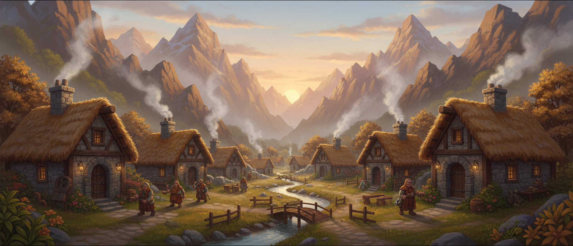
Two skins over one world, or two worlds
A tileset ground and a blended ground are not two skins over one model of the world. They are two models.
The tileset draws a sprite per tile and a transition sprite where two types meet. The blended ground draws a handful of tiling material textures mixed through a continuous coverage field, so the line between grass and dirt has no fixed relationship to the grid at all. Every boundary is a contour, and a contour can be any shape.
That difference costs more than appearance. Maps imported from a later generation of RTS carry terrain types that no transition sprite in this project covers, so the 2D renderer simply could not put their ground on screen. Unifying both renderers on one texture set was as much about that as about matching colours, and it is why the importer can finally show its work in both modes.
What the coverage field stores
The coverage field is one array that both renderers read and neither owns. It is what a terrain system would usually call a blend map or a weight map: an RGBA byte array at a few texels per tile, where each channel holds how much of one material covers that point.
| Channel | Layer |
|---|---|
| R | Dirt |
| G | Forest floor |
| B | Grass |
| A | Water |
Rock gets no channel. It is the opaque base underneath everything, so rock is what shows through where all four stored layers are low.
Coverage is not an occupancy mask with a blur over it. Each point stores its true straight-line distance to the nearest tile of that material. Computing that for every point at once is a well-studied problem called the distance transform, and the algorithm used here is Felzenszwalb and Huttenlocher's: it gets the exact answer in two cheap one-dimensional passes, one down the columns and one across the rows, rather than by measuring every point against every tile.
That distance is then pushed through a smooth ramp against seeded noise with a domain warp, meaning the noise is used to distort the coordinates before they are read rather than merely added to the result, which is what turns a mathematically perfect contour into one that looks eroded.
The cheap alternative to a true distance transform, a 3x3 chamfer distance, approximates the distance by hopping neighbour to neighbour. It puts octagonal facets on every equal-distance contour, and coastlines come out looking like diamonds.
Building the field twice a map was a one second freeze
One object owns the field, the macro tint, the relief sheet, the texture set and the random seed. Both renderers ask that object for the ground, keyed on the identity of the map it came from, so whichever asks second gets the first one's work for free.
The reason is a trailer capture mode that renders both pipelines in the same frame. Two independently seeded fields would not only cost double, they would look different from each other in the same shot, with nothing in the map to explain why. Double is expensive on its own. A timing pass taken before any of this was built measured a synchronous field rebuild on an M3 Pro at three map sizes:
| Map | Texels per tile | Build | Field size |
|---|---|---|---|
| 96² | 8 | 143 ms | 2.25 MB |
| 256² | 8 | 959 ms | 16.00 MB |
| 256² | 4 | 199 ms | 4.00 MB |
At 8 texels per tile a 256-tile map is a one second freeze on load, and the boot path built the ground twice, so it was really two seconds. The fix is a cap that scales resolution down as maps get bigger: 8 texels per tile up to 128 tiles, 6 up to 176, 4 above that. On the largest maps the edge between two materials quantises at 8 world pixels instead of 4, which linear filtering and the game's camera distance hide completely.
The failure a test could not have caught
The 2D renderer used to break up texture repetition by picking a rotated variant of the ground texture per 4x4 block of tiles. A hard change of texture coordinates on a block boundary does not read as variation. It reads as a square patch of different ground, and at the distance an RTS camera sits, those patches are big enough to look like a bug in the map generator.
No test caught it and no test could have. Every pixel was exactly what the code asked for. It was caught by eye, in the 2D half of the split view, sitting next to the 3D half. That is the entire reason the split view draws both at once. The 2D path now lays down one continuous world-space pattern and breaks the repeat with the shared macro tint, a relief sheet and procedural noise instead.
Two numbers came out of the same pass. Moving macro variation, lighting and procedural detail onto an 8 pixel lattice took a chunk bake from 22 ms to 12 ms, with a maximum difference of one code value per colour channel, checked by pixel diff rather than by eye. Baking chunks nearest the viewport first, with a flat colour fill standing in until each one is ready, turned a predicted 180 to 260 ms stall on a cold map into a five-frame ramp that goes unnoticed.
Keeping two renderers in agreement
Ground that dry and ground that green come out of the same field and the same colour grading. Anyone maintaining a canvas fallback beside a WebGL path, or a server-rendered preview beside a live view, has this problem. Three rules came out of solving it, and the first does most of the work.
Neither renderer may own the data. A third object owns it, and both renderers acquire the same instance, keyed on the identity of the thing it was derived from rather than on a string name, so a reload cannot collide with a stale cache entry. Whichever renderer asks second pays nothing. That is roughly a dozen lines of code and it makes disagreement structurally impossible instead of merely unlikely.
Every shared constant lives once, in the host language, and reaches the shader by string interpolation rather than by being retyped into GLSL. A uniform works too, and gives you one more thing to forget to upload. A literal typed into the shader source is a second copy by definition:
export const GRADE = { gain: 1.12, lift: 0.06, saturation: 0.92 } as const;

export const GRADE_GLSL = /* glsl */ `
vec3 gradeLayer(vec3 c) {
  // toFixed, never the bare number: a value that happens to be 1 interpolates
  // as "1", which is an int in GLSL, and vec3 * int does not compile.
  c = c * ${GRADE.gain.toFixed(4)} + ${GRADE.lift.toFixed(4)};
  float l = dot(c, vec3(0.2126, 0.7152, 0.0722));
  return mix(vec3(l), c, ${GRADE.saturation.toFixed(4)});
}`;
That matters here because the shader is not the only consumer. A map preview thumbnail cannot run a ground shader, and neither can the minimap or the ring of off-map horizon drawn beyond the playable area. All three replay the same grading maths in plain TypeScript, reading the same constants the shader compiles in. It is why the edge of the map does not step in colour against the map itself.
Write down every expression computed identically in both paths and stored nowhere. That list is the surface the two can drift along, and it is short enough to enumerate in a sentence. The rule generalises past renderers: any value derived twice from shared inputs, rather than stored once, is a value two call sites can start disagreeing about without either of them changing.
One decision inside that chain matters for anyone doing the same port. Everything is mixed in sRGB. The ground textures are tagged as carrying no colour space and the encode step is replaced with a no-op, so the material does not re-encode them on the way out. Mixing in linear space is more correct, and it made every 3D blend band read darker and softer than the same band in the 2D view. Canvas has no linear mode, and 2D is the primary renderer, so 3D matches 2D rather than the other way round.
Where the two deliberately part company
Anti-repetition is the one place agreement was not the goal. The 3D path packs each material's variants into a texture array and picks a variant per irregular, warped patch of ground, with its own rotation, mirror, phase and slight scale change, cross-fading only inside a narrow border where patches meet. I ported that sampler to canvas to close the gap, and timed one chunk bake with it on against the same bake with it off. About 316 ms per chunk. That is not a fallback renderer, it is a slideshow. The 2D path exists to serve machines without WebGL, so it keeps one continuous pattern and takes its variation from cheaper sources.
The same coverage field is what lets the ground carry elevation at all, because a coverage pass that ignores height paints dirt straight up a cliff face. That is making cliffs real terrain instead of invisible walls. Sharing one texture source has a memory cost of the same kind as the one that took a browser tab out of memory, and the shader that composites all of it sits against a hard ceiling described in the WebGL limit that turns your terrain white.
Next on the ground is the material set itself. Nine biomes now share the same four channels, and a few of them want a fifth material that the current channel layout has no room for.


